Difference between revisions of "How To"
(→Setup a RS-232 Passive Listener (PL) Device) |
(→Setup Binary-Coded Decimal (BCD) Devices) |
||
| Line 175: | Line 175: | ||
:<span style="color:blue">'''Caution!'''</span> There are no USB to Parallel adapters that have been found to work (so far). USB to parallel adapters only work with printers. | :<span style="color:blue">'''Caution!'''</span> There are no USB to Parallel adapters that have been found to work (so far). USB to parallel adapters only work with printers. | ||
---- | ---- | ||
| − | *<span style="color:red;font-size: 125%">'''Windows 7 Users'''</span> - Make sure to setup the '''DDUtil''' desktop icon to run in '''XP Compatibility Mode'''. | + | *<span style="color:red;font-size: 125%">'''Windows 7/8/10 Users'''</span> - Make sure to setup the '''DDUtil''' desktop icon to run in '''XP Compatibility Mode'''. |
** Right-click the '''DDUtil''' desktop icon and select '''properties'''. | ** Right-click the '''DDUtil''' desktop icon and select '''properties'''. | ||
** Select the '''Compatibility''' tab. | ** Select the '''Compatibility''' tab. | ||
Revision as of 15:18, 24 September 2016
This section is intended to serve as a guide for setup and configuration of the different features of DDUtil. If you have a configuration that is not shown here or if you have questions about how to setup and/or configure DDUtil please contact the author for assistance. Additionally, you can ask questions and get support from the DDUtil Yahoo support group.
Contents
- 1 Setup a ACOM2000A Linear Amplifier
- 2 Setup Binary-Coded Decimal (BCD) Devices
- 3 Setup DDUtil to work with PowerSDR
- 4 Setup a ICOM IC-PW1 Linear Amplifier
- 5 Setup Macro Commands
- 6 Setup a microHAM Band Decoder
- 7 Setup a RS-232 Passive Listener (PL) Device
- 8 Setup a Radio Control Program (RCP)
- 9 Setup a Remote Tuner
- 10 Setup Rotor Functions
- 11 Setup a SteppIR Antenna Controller
- 12 Starting Multiple Programs using Windows Scripting Host
- 13 Using VSP Manager and MicroHam Router
- 14 Virtual Serial Port Planning
- 15 References
Setup a ACOM2000A Linear Amplifier
Features
DDUtil supports the following features and operations of the ACOM A2000A.
- Follows radio Frequency and Band Changes.
- Auto Power On if optional Remote On Adapter is installed.
- StandBy/Operate mode selection.
- Auto Tune of single and multiple bands.
- Antenna Selection if optional A2000S is installed.
- Tube Temperature display.
- Frequency and Band/Segment display.
- User/Default amplifier tuning display.
Setting up the ACOM 2000A HF linear amplifier is straight forward and easy. It shares the same space as the Alpha 87A in the bottom portion of the Amps Tab.
Setup
- In DDUtil's Options menu, selecting ACOM 2000A from Tube Amplifiers item will automatically setup all the parameters required for this amplifier. See the following subjects for information on configuring the various features of the ACOM 2000A.
Connections
There are two possible different PC serial cable configurations depending on whether or not you are using the Remote-On Adapter.
Warning!
Pins 1 and 9 must not be connected in either cable. Your PC port can be damaged. ACOM uses those pins to supply 48vdc to the RCU (Remote Control Unit).
Here are the PC serial cable connections for the different configurations.
NO Options Installed
PC <--> A2000A (RS232 plug)
1 no connection!
2 - 3
3 - 2
5 - 5
9 no connection!
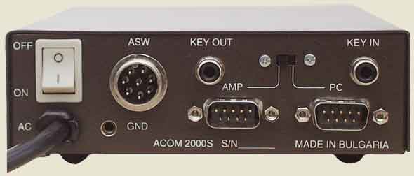
Remote-On Adapter installed
PC <--> Remote On Adapter (PC plug)
1 no connection!
2 - 3
3 - 2
4 - 6
5 - 5
6 - 4
7 - 8
8 - 7
9 no connection!
Dummy DB9F with pins 2,3 shorted (A2000S plug)
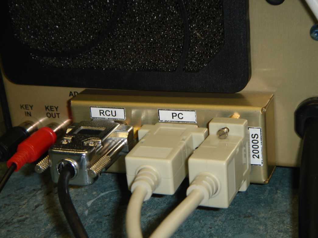
A2000S Antenna Selector Installed
PC <--> A2000S (PC connector)
1 no connection!
2 - 3
3 - 2
5 - 5
9 no connection!
Remote-On Adapter & A2000S Antenna Selector Installed
PC <--> Remote On adapter (PC connector)
1 no connection!
2 - 3
3 - 2
4 - 6
5 - 5
6 - 4
7 - 8
8 - 7
9 no connection!
Alert!
See the following drawings for additional connection and configuration information.
Please Note: Careful attention is required to the following drawings. The right cables are vital for correct operation.
A2000S Antenna Selector Wiring
Remote On Adapter Wiring
Controls Description
- Serial Port
- Select the hardware serial port to which the amplifier is connected. Note: A port must be selected before the amplifier may be enabled.
- Enable
- Select the Enable check box to allow use of the amplifier.
- Baud Rate
- Select the baud rate of 1200 for this amplifier.
- Air Temp
- Displays the average temperature of the two tubes to the closest 10 deg. C (30C, 40C, 50C).
- Freq
- Displays the last frequency sent to the amplifier.
- Power
- Pressing this button toggles the amplifier's Mains Power On/Off if the ACOM Remote-On Adapter is installed. If the adapter is not installed only the Off function is operable.
- Operate
- Pressing this button toggles the amplifier's Operate/StandBy mode .
- Auto Tune
- Pressing this button starts the amplifier's Auto Tune procedure. Select the bands you wish to Auto Tune in the Bands group before pressing this button. See the Auto Tune section below for setup and operation.
- HV
- Displays the amplifier's High Voltage status (On/Off).
- Band
- Displays the current Band (160M-10M) the amplifier is tuned for.
- Seg
- Displays the current Band Segment the amplifier is set to.
- Message Window
- Displays various messages including Errors, Status Messages and Auto Tune success or failure messages.
- Ant
- When equipped with an optional ACOM A2000S ACU (Antenna Control Unit), this window will control assignment and display the current antenna attached to the ACU. Double-click to increment the antenna selection (0-9).
- If not ACU equipped, this window is disabled and will display the number one (1).
- User
- Displays whether the amplifier will use Default (factory) or User (auto tune) Load and Tune settings for the current Band, Segment (and Antenna if ACU equipped).
Note!
- An abbreviated display is available by using the Mini Window feature and may be accessed by opening the Tools menu and selecting Show Mini Window or pressing the short cut keys Alt+M while DDUtil has focus.
Bands Group
This group is where you select which bands you wish the Auto Tune procedure to include. These bands can be all selected at once or one at a time as desired.
- Info
- Press this button to bring up this document.
- Tune Level
- Used during the Auto Tune procedure to set the Tune drive level. This value is adjustable from 10 - 20 watts and will need to be varied from amp to amp and band to band as needed to achieve a successful Auto Tune operation. A value of 11 or 12 is a good starting point.
- Chk All (Select All)
- Press this button to Select all bands.
- Clr All (Clear All)
- Press this button to Clear all bands.
Auto Tune Procedure
- Caution Please Read!
- This procedure places the Flex radio and the ACOM 2000A into transmit mode and produces RF power output. Serious consequences are possible if a through understanding of these procedures are not realized and followed. If you don't understand or have doubts about this procedure DO NOT attempt to use the procedure and contact the author for assistance.
- A good practice is to use a Dummy Load until familiar with this feature. That way a 50 ohm load is always applied to the ACOM 2000A.
- If any of the following items are true you can only use the Auto Tune procedure on one band at a time.
- A2000S Antenna Control Unit installed (multi band auto tune just isn't reliable).
- SteppIR Antennas (due to the time it takes to re-tune the antenna).
- Antenna Tuner (due to the time it takes to re-tune the tuner).
- Slow Reacting Antenna Switches (if it takes longer than 2 seconds to switch).
- Repeated Auto Tune Failures
- Avoid any condition where an open or non-resonant antenna could be presented to the ACOM 2000A.
- The following represent conditions where multi-band selection is ok to use with the Auto Tune procedure.
- Multi-Band antennas with one feed line such as Log Periodics, HyGain HyTower or Trap antennas.
- Fast acting antenna switches such as the microHAM Band Decoder.
- If any of the following items are true you can only use the Auto Tune procedure on one band at a time.
Setup
- Set the Auto Tune Drive Level to produce a Lite Bar reading of between 4 and 8 as per the ACOM manual section 4-1 Auto Tune procedure.
- Select the bands you want to Auto Tune based on the guidelines above and what antennas you want to use.
- Set the radio to the frequency you want the amplifier to Auto Tune for each band.
- Make sure the amplifier is on, warmed up and in Operate mode.
- Press the Auto Tune button in the ACOM 2000A group.
Response
- See the Message window for success or failure messages for each band attempted. This window is scrollable for about fifty (50) messages so all band responses should be visible.
Failures
- The ACOM 2000A amplifier is very picky about the drive level before and during the Auto Tune process. Most failures are probably going to be due to drive related issues so don't be alarmed if you have one or more failures when several bands are selected.
- If there is a failure when running a group of several bands, try selecting just one band by itself and it will probably run successfully.
Options
Two (2) ACOM equipment options are supported by DDUtil for the ACOM 2000A and are included in the general discussions of the ACOM 2000A.
- ACOM 2000S/SW - Ten (10) position remote antenna switch. This is a first class piece of hardware that inter-operates seamlessly with the ACOM 2000A amplifier.
- Remote On adapter. This adapter allows the AC mains to be remotely turned on for the ACOM 2000A. This adapter plus the advanced features of the ACOM 2000A allow for real Remote-Site operation of this amplifier.
A2000S Antenna Switch Operation
The A2000S antenna switch has two (2) modes of operation depending on whether the amplifier is powered On or Off.
- When the amplifier is On antenna assignments are sent to the switch from internal memory in the ACOM 2000A amplifier.
- When the amplifier is Off antenna assignments are stored in DDUtil and sent to the A2000S during band changes.
- Note: This feature is only available when the amplifier is Off. Normal operation resumes when the amplifier is powered On.
The second option allows the user to have auto antenna selection when the amplifier is powered off which is normally not possible. To use this feature follow these instructions.
- Select Acom Ant Default from the Options menu.
- Select the antenna number desired for each band.
- Select the Enable check box.
Setup Binary-Coded Decimal (BCD) Devices
- On the Ports tab in the Parallel Port group select your port number.
- If you are using a PC with a mother board port you can get the LPT number from the Device Manager see the Port Locator further down this page.
- If you are using a PC with a add-on card see this link for how to find it's address.
- Caution! There are no USB to Parallel adapters that have been found to work (so far). USB to parallel adapters only work with printers.
- Windows 7/8/10 Users - Make sure to setup the DDUtil desktop icon to run in XP Compatibility Mode.
- Right-click the DDUtil desktop icon and select properties.
- Select the Compatibility tab.
- Check the Run this program in compatibility mode check box.
- Choose the Windows XP Service Pack 3 option.
- Alert! - Non-compliance will result in NO Parallel Port Output.
- Set up a data file for DDUtil to read for the BCD device.
- Go to the BCD tab on the DDUtil form and follow the following steps. Note: If you are using a Yaesu Quadra amplifier or a DX Engineering CC-8 antenna switch the file included with DDUtil is correctly formated and the following file editing steps can be skipped.
- After consulting your owners manual, edit the BCD data file to obtain the correct values for your device. Editing may be done right in DDUtil or in any other XML editor of your choice.
- Place the edited file in a directory of your choice, but it is recommended to use the application root directory (usually C:\Program Files\DDUtil\). If the file is edited in DDUtil it may be saved in the Data File group by pressing the Select button, selecting the desired directory and giving it an appropriate name and pressing save. The file name will be remembered by DDUtil and loaded each time the progam starts.
- Check the Enabled check box to turn the function on.
- Go to the BCD tab on the DDUtil form and follow the following steps. Note: If you are using a Yaesu Quadra amplifier or a DX Engineering CC-8 antenna switch the file included with DDUtil is correctly formated and the following file editing steps can be skipped.
- Back on the Ports Tab check the Enable check box to complete the BCD device setup.
- Note: see the following topics for discussions on various aspects of BCD setup and operation.
- BCD Data File Format
- BCD Data Port
- Most BCD driven devices I have been associated with only use 3-5 control lines. My Quadra uses four (4) control lines. It is entirely conceivable that two (2) BCD devices could be run off of one (1) LPT port. As an example hook device 1 to port pins 2-5 and device 2 to pins 6-9. Set up the data file for say 20 meters using (14100, 85) instead of (14100, 5) and it will produce 01010101 instead of 00000101 at the parallel port which is a binary 5 for each device.
- Inter-Connecting Cables
- Parallel port cables will have to be fabricated by the user for his particular hardware setup. A sample cable drawing is available to serve as a guide.
- If you would like to see how this concept works without setting up a binary device you can build a small LED array that can connect to your parallel port and show the binary code being sent. You can watch the LEDs change as the frequency changes.
- Port Locater
If you don't know what ports are installed on your pc the following procedure will tell you.
- From the Start button select Control Panel
- Select System
- Select Hardware
- Select Device Manager
- Expand the Ports entry, all your hardware ports will be listed there.

Note: If you are using a non-motherboard port then a different approach is necessary for getting the port address. This link will help you get the port address you will need.
Setup DDUtil to work with PowerSDR
- Setup a pair of VCOM serial ports. As an example lets use ports Com10 and Com11 one for DDUtil (Com10) and one for the radio (Com11). Of course, substitute your port choices for these when you do yours for real. If you are not familiar with this process, refer to the Flex Knowledge Base article for how to setup virtual serial ports.
- On the Ports tab of DDUtil, in the Serial Ports group, select COM10 for the Radio CAT port.
- In the PowerSDR console, from the program menu, open the Setup form.
- Select the CAT Control tab.
- In the CAT Control group, un-select Enable CAT.
- In the CAT Control group, from the Port drop-down list box select the matching port Com11 for the port pair selected above
- In the CAT Control group, select Enable CAT.
- Select the CAT Control tab.
Setup a ICOM IC-PW1 Linear Amplifier
- Connect a CT-17 or other CI-V level converter device from the PC's hardware serial port to the IC-PW1.
- In DDutil, on the Other tab in the IC-PW1 group, perform the following actions.
- Select the port number you connected the level converter to in the above step.
- The CI-V (ra) address is not user configurable and is set by the IC-PW1 amplifier. It is shown for information purposes only.
- Set the CI-V (ta)[1] (DDUtil) address to use. Unless you have a reason to use another address use the default address (33h) provided by DDUtil.
- Check the Enabled check box to complete the DDutil portion of the setup.
- Leave the Disable Broadcast check box un-checked.
- Bring up PowerSDR and DDUtil and verify they are operating normally. There should be frequency data in the DDUtil Title Bar when operating correctly.
- On the PW1 amplifier perform the following actions:
- Refer to the ICOM IC-PW1 Instruction Manual section 3 ("Programming the CI-V Address") and perform the following procedure. Note: This procedure is mandatory for the PW1 to track PSDR frequency. This only takes a few seconds and only has to be done once, normally.
- Remove all connections from the PW1's ACC-1 connector.
- While simultaneously pushing your PW-1's UP, and DOWN buttons, push its POWER button.
- Power-down the PW1.
- While pushing your PW1's INPUT button, push its POWER button which places your PW1 in programming mode. The INPUT 1 light will begin blinking. If after 10 seconds the the INPUT 1 light has not stopped blinking, change the PSDR frequency slightly to force DDUtil to send frequency data to the PW1. The INPUT 1 light should now be glowing steadly indicating that PW-1 programming is complete.
- Push your PW1's POWER button to record the programming results and power off your PW1.
- Reattach the PW1's ACC-1 connector.
- Push your PW1's POWER button to power on your PW1, which will from now on track your transceiver's frequency.
- Refer to the ICOM IC-PW1 Instruction Manual section 3 ("Programming the CI-V Address") and perform the following procedure. Note: This procedure is mandatory for the PW1 to track PSDR frequency. This only takes a few seconds and only has to be done once, normally.
- If the above procedure was successful your IC-PW1 amplifier should indicate the correct band and should now follow PowerSDR from band to band.
Notes:
- Most single CI-V adapters require that either RTS and/or DTR line(s) be selected in order to power the adapter from the PC. See the manufacturers documentation for additionl information/requirements.
- Click here for a technical discussion of CI-V operation as related to the IC-PW1 Linear Amplifer.
Setup Macro Commands
Macros are a great time saver when operating. You can setup the Macro buttons to perform actions on the radio that would require many mouse moves to do manually. If you follow the steps below you shouldn't have any problems setting up your Macros.
Planning
Some thought needs to given to the order of instructions you want to send to the radio. For instance you don't want to tell the radio to set a filter and mode before changing bands as changing bands will nullify these settings. PowerSDR keeps track of a lot of settings based on the Band Stack which could change your intended action so always change the frequency first. A sample plan to move the radio to 80 meters AM mode could be:
- Set Frequency (3,980)
- Set Mode (AM)
- Set Power Level (50 watts)
- Set Filter (6.6 kHz)
- Set Meter Function (Mic)
- Set Transmit Profile (AM)
Or whatever your requirements might be for a particular operating band and mode.
Programming
The next step is to figure out what CAT commands are needed to carry out the intended Macro function. At this point if you are new to CAT commands it would be wise to go to the CAT section and get familiar with what CAT commands are and how to use them. Then you can come back here and continue programming your first Macro.
- The first thing you will need is a list of the CAT commands. If you don't have a copy there is one available here.
- Open the Macro tab in DDUtil. If the Data Grid is not showing left click with your mouse on any open area of the tab to unhide it. Notice the Data Grid is made up of columns and rows and is similar to an Excel spreadsheet. In the left most column of each row is a M number (Mn) that equates to the Macro number this row represents. There are a total of twelve (12) rows equating to twelve (12) macros/buttons.
- In the Button column, select the button number you want to use for this Macro and type in the name you want to appear on the button. In this sample case use 80 AM. Keep the name short or it won't fit on the button face. Notice that after exiting the cell you were editing the button face text changes to match what you typed in the button cell.
- In the Command column enter the commands in the order you want them executed making sure a semicolon (;) is inserted after each command else the command will fail. The following commands are shown with {comments} for demonstration purposes, don't use the {comments} in your code.
ZZFA00003980000; {Set Frequency (3,980 kHz) - 16 chars.}
ZZMD06;          {Set Mode (AM) - 7 chars.}
ZZFI04;          {Set RX Filter (6.6 kHz) 7 - chars.}
ZZMT02;          {Set Meter Function - 7 chars.}
ZZTP02;          {Set Transmit Profile (AM) - 7 chars.}
ZZPC050;         {Set PA Drive Level (50 watts) - 8 chars.}

The command string should look like the following line (no spaces between commands).
ZZFA00003980000;ZZMD06;ZZPC050;ZZFI04;ZZMT02;ZZTP02;
The rest of the Macro buttons program exactly the same way as the one shown above.
As far as we know, there's no limit to command combinations that are possible. Just remember to follow the above procedures and if you have a problem use the CAT Command Test Form in PowerSDR to test individual commands.
Programming Note:
If using the Transmit Profile (ZZTPnn) command be advised this command will set the Power Level to what is stored in the Transmit Profile.If you want some other Power level, set it after you set the Transmit Profile. Or, always set the Power Level as the last command in the macro.
Testing
Testing may be accomplished in one of two (2) ways.
Individual Commands
It is recommended that each command be tested in the PowerSDR CAT command tester prior to loading into the Data Grid editor. To access the tester open the Setup menu select the CAT Control tab and press the Test button. The CAT Command Tester form will appear. To test your command:
- Enter the command into the CAT Command text box including the semicolon (;).
- Press the Execute button while observing the radio console.
- You should see the appropriate action take place on the radio for the command you entered.
- Note: that there won't be a CAT Response message for these commands as they are all SET commands and not Read commands which are the only ones that get responses.
Command String
Once you have entered the commands into the Data Grid and saved the file it's time to test your work. While watching the radio console do one of the following.
- On the Macro tab of DDUtil press the designated button for the macro you wish to run.
- While DDUtil has focus press the designated F key for the macro you wish to run.
While both methods achieve the same results I find the F key method to be my favorite.
If the desired results didn't happen you probably have a syntax error in the command that failed or you forgot the semicolon (;) termination character.. Check it carefully and/or use the CAT Command Test Form in PowerSDR to test individual commands.
Please report any errors or failures to the DDUtil reflector or the author.
Save Your Data
Once you are satisfied with the commands or progressively as you write them, you will need to save the macros as a file. Then the file will be loaded automatically when DDUtil starts in the future. You can save the file anywhere you want, but it is recommended to save macro files along with the other DDUtil files in the DDUtil base directory which is typically C:\Program Files\DDUtil\. The default file name is MacroData.xml, but you can use any name you wish. After modifing your macro commands to your liking, take the following action.
- Change the File Name to a unique name if you want to keep the original file intact. Unique file names could be MacroDataContest.xml or macroDataSSB.xml or any other meaningful name to help you remember it's function.
- Press the Save button.
Setup a microHAM Band Decoder
- On the Repeater Group of the RCP tab
- Set the port number and baud rate.
- Select Normal as the data type.
- MicroHAM Device Configurator software:
- Select Kenwood TS 2000 as the RIG (band data source.
- Press the Advanced Settings button on the bottom left corner of the form.
- In the Band data source tab select the following parameters.
- Rig Interface = RS232
- Baud Rate to match the setting in Repeater using the highest rate possible.
- In the Configuration Menu select Write to Device to save the new configuration to the decoder.
- MicroHam Band Decoder
- Connect a Null Modem cable to the RS232 port on the decoder and to a PC port. In the decoder manual this cable is identified as RIG232.
Setup a RS-232 Passive Listener (PL) Device
- On the Ports tab of DDUtil perform the following actions.
- In the Passive Listener group, select the hardware port you want to connect your PL (Passive Listener) device to.
- Select the correct communication parameter from the PL/Radio Comm drop-down control at the bottom of the form.
- Make sure your hardware is setup to match the DDUtil communication parameters.
- Radio Type = Kenwood (specific model TS-2000, if there's a choice).
- Baud, Bits, Parity & Stop Bits to match the PL/Radio Comm control in DDUtil.
- If using a microHam Band Decoder, in the configuration menu check the Stop Polling, use auto information check box.
- See your owners manual for the type of cable to use. For building your own cable see this sample cable drawing.
- If the Passive Listener device you're connecting is a Slave Radio:
- Select the Follow Radio check box.
- Select the radio you want to connect from the Radio Type drop-down.
- None → Late model Yaesu (sends Kenwood IF reply).
- Kenwood → Kenwood (sends FA reply).
- Yaesu Type I → FT1000, FT100.
- Yaesu Type II → FT897,FT857,FT847,FT817.
- Yaesu Type III → FT450, FT950.
- Icom → All Icom radios (CI-V).
- Select DTR or RTS check boxes if your CI-V to Serial Adapter needs power from the serial port.
- Put the address for your radio in the CI-V Address box. Note: Use 00 to broadcast to all connected devices.
- SO2Rxlat → SO2Rxlat serial to parallel interface.
- JARL 2000F → JARL 2000F Amplifier.
Setup a Radio Control Program (RCP)
Note! see the Ports tab of the Setup form for discussions on settings and tips for some of the various RCP programs that are known to run with DDUtil.
RCP #1
- Setup a pair of virtual serial ports. As an example lets use Com4 and Com5 one for the Radio Control Program (Com 4) and one for DDUtil (Com 5). In actuality it does not make any difference which port number goes to what application, they don't know the difference. Of course, substitute your port choices for these when you do yours for real. If you are not familiar with this process, refer to the Flex Knowledge Base article for how to setup virtual serial ports.
- On the Ports tab of DDUtil, in the Serial Ports group, select COM5 for the RCP port.
- In the setup section of your RCP perform the following actions.
- Select a port (Com 4) for the CAT communication serial port. You can disregard the other comm parameters as virtual serial ports don't use them.
- Set the polling interval for this program to query PowerSDR for frequency and/or mode information. Typically, this interval is 200 ~ 500 MS depending on how quickly you want the data picked up by DDUtil and relayed to its clients.
RCP #2~4
Caution!
Normally, RCP #1 is setup first due to the fact you don't want more than one program regularly polling the radio for frequency data. If RCP1 is setup DDUtil's internal polling is disabled. Not all RCP's poll the radio regularly and may only send commands to the radio when they want to know specific data. This is not good if you have a piece of equipment like an amplifier or tuner connected that expects up to date frequency data.
- Setup a pair of virtual serial ports for each additional RCP you wish to install. As an example lets use Com14 and Com15 one for the RCP (Com15) and one for DDUtil (Com14). In actuality it does not make any difference which port number goes to what application, they don't know the difference. Substitute your port choices for these when you do yours for real.
- On the RCP tab of DDUtil perform these actions for the RCP you wish to enable.
- Select the port (Com14) you wish to use for this RCP.
- Check the Enabled check box to complete the setup process for this RCP
- In the setup section of your RCP perform the following actions.
- Select a port (Com15) for the CAT communication serial port. You can disregard the other comm parameters as virtual serial ports don't use them.
- Set the polling interval for this program to query PowerSDR for frequency and/or mode information. Typically, this interval is 100 ~ 500 MS depending on how quickly you want the data picked up by DDUtil and relayed to its clients.
Note: Use the above processes for additional RCPs (3,4) substituting correct port numbers as required.
Operation Notes:
---------------
- There is a known problem when using DDUtil with MixW, HRD and some other 3rd party RCP
  software with regards to the DTR, RTS and other signal lines. These programs default some
  or all the control lines to Always On or Active. These control lines must be set to
  Always Off or Inactive for communication to flow between the pair ports.
Setup a Remote Tuner
See the Tune Detect page for detailed information on this subject.
Setup Rotor Functions
DDUtil has two (2) methods of Rotor implementation.
Direct Control
This method is where the user looks up a heading on the Rotor tab and manually turns the Rotor by pressing the SP or LP button. This is the method employed by most users.
Direct Control Implementation
- On the Setup tab take the following actions:
- Model - Select the rotor model you are using.
- Speed - Select a speed setting if your rotor (M2, Yaesu) is one of the models that require a speed be set.
- Serial Port - Select the hardware serial port your rotor control box is connected to.
- Com Data - From the drop down list select the proper communication setting to match your rotor controller.
- Enable - Select the Enable check box to complete the Rotor setup.
On the Rotor tab take one of the following actions:
- Find the bearing to the station you want and press the SP or LP buttons.
- Type the bearing into the SP or LP bearing text box and press the appropriate button.
RCP Rotor Pass Thru
This method is where you have one or more RCP's that have Rotor capability and you wish to pass Rotor bearings to DDUtil.
This reasoning could be you're running a suite of programs such as DXLab which has auto station look up based on either Telnet spots or a digital program that reads the station call and furnishes the Rotor bearing to the station for you.
RCP Rotor Pass Thru Implementation
- On the DDUtil Setup tab take the following actions:
- Model - Select the rotor model you are using.
- Speed - Select a speed setting if your rotor (M2, Yaesu) is one of the models that require a speed be set.
- Serial Port - Select the hardware serial port your rotor control box is connected to.
- Com Data - From the drop down list select the proper communication setting to match your rotor controller.
- Enable - Select the Enable check box to complete the Rotor setup.
- In the appropriate DDUtil RCP setup, select the proper serial port pair end that connects to the RCP Rotor serial port.
- In the RCP preform these actions;
- Select the proper serial port pair end that connects to the DDUtil Rotor port.
- Select *ONLY* HyGain or Idiom Press as the rotor type. DO NOT select any other rotor type. DDUtil will convert the HyGain protocol to your rotor type.
- Repeat steps 2 & 3 for each RCP you want to use.
In the Pass Thru implementation no other action is required by the user, at least related to DDUtil. All other actions are passed by the RCP being used.
Below is a representation of the process.
RCP sends rotor commands to its port (Com10)
                 |
                 v
RCP rotor port Com10 <--> DDUtil RCP1 rotor port Com11 (vCom)
                            |
                            v
DDUtil sends to it's rotor port Com1 (the hardware)
Setup a SteppIR Antenna Controller
There are two (2) possible options for controlling a SteppIR antenna controller.
- Passive Listener, i.e. DDUtil broadcasts transmit frequency via the PL port to the antenna controller and expects no response from the controller.
- Connect from the SteppIR control box Data-In port (top connector) via special cable to the Passive Listener port of the PC. This cable can either be procured from SteppIR or fabricated by the user. See this sample cable drawing.
- In DDUtil on the Ports Tab in the Serial Ports group take the following actions:
- Select a port number for the Passive Listener serial port.
- Select the communication parameters to match the SteppIR control box settings in the PL/Radio Comm drop-down box at the bottom of this Ports Tab .
- Interactive Mode, i.e. DDUtil sends frequency data to the antenna controller and expects to receive a response from the controller. If the frequency has changed since the last polling period. A request is sent to the controller for motor status. If the response says the antenna is moving, DDUtil will inhibit the Flex-5000 from transmitting until the tuning is complete.
- Connect the SteppIR control box Data-Out port (lower connector), via a Null Modem cable or user fabricated cable, to an unused serial port on the PC.
- Note: DO NOT use the Passive Listener port on the Ports tab.
- In DDUtil on the Other Tab in the SteppIR group take the following actions:
- Select the port number you want to use for the SteppIR controller.
- Set the Interval setting to between 500 - 1000 Ms.
- Select the Enable check box.
- Connect the SteppIR control box Data-Out port (lower connector), via a Null Modem cable or user fabricated cable, to an unused serial port on the PC.
Starting Multiple Programs using Windows Scripting Host
Most of us need to run several ancillary programs in addition to PowerSDR. Below is a script file that starts multiple programs in desired order and with needed delays between each.
- Using Notepad or other suitable plain text editor create a file and insert your version of the following commands into this file.
Note: The Sleep statements are in milliseconds (1000 = 1 second).
Note: Your file and/or path names may be different, adjust accordingly.
Dim WshShell
Set WshShell = WScript.CreateObject("WScript.Shell")

WshShell.Exec("C:\Documents and Settings\Steve\Desktop\Repos_PALPB\PowerSDR.exe")
WScript.Sleep(10000)
WshShell.Exec("C:\DDUtil\DataDecoder.exe")
WScript.Sleep(5000)
WshShell.Exec("C:\Afreet\CwSkimmer\CwSkimmer.exe autostart")
WScript.Sleep(1000)
WshShell.Exec("C:\Program Files\MRP40 Morse Decoder\MRP40v61.exe")
WScript.Sleep(1000)
WshShell.Exec("C:\Program Files\DXLab Suite\Launcher\DXLabLauncher.exe")
The above script does the following:
- starts PowerSDR
- waits 10 seconds
- starts DDUtil
- waits 5 seconds
- starts CW Skimmer
- waits 1 second
- starts MRP40
- waits 1 second
- starts the DXLab Launcher
- Save the file with a .vbs extension (sdrStart.vbs) and place it on your desktop.
- To execute the file use one of the following methods.
- Double-click the file name on the desktop.
- Open a command window and type in the path and name and press enter.
- Create a batch file (.bat) and include the following statement wscript.exe sdrStart.vbs.
Note: Batch files are more flexible as they can be can be called from short-cuts and run better in high security environments.
Using VSP Manager and MicroHam Router
- Due to the fact that they both use the same Eltima drivers they both can't be open at the same time or conflicts/errors will result. However, they both can be used together on the same system if the following rules are observed.
- If you want to run VSPM then disable the Microham Router.
- If you want to run Microham Router close the VSPM GUI.
- After port pairs are created the VSPM GUI can be closed as there is no additional need for it unless you need to add or delete port pairs.
Note: VSPM only needs to be open during port pair creation or for port deletion or maintenance. Otherwise, VSPM can/should be closed.
Virtual Serial Port Planning
Some thought needs to be given on how to setup the virtual port pairs you are going to use. If you are planning to use DDUtil as more than a passive listener control for your amp or tuner the following thoughts are offered for your consideration.
- Think out what programs you will be running as some Radio Control Programs are limited as to how high of a port number it will use. Lay out all the programs and note the port limitations if any.
- Virtual port assignment also has to consider how many hardware ports are attached or may be attached to your PC. If you will be adding additional serial ports you will need to allow for this.
Below is a listing of how this could be done and is shown as an example only.
Com  Type    Function
---  ----    --------
 1   Hdwe    spare
 2   Hdwe    Passive Listener
 3   Hdwe    Rotor
 4   Hdwe    LP-100
 5   Hdwe    SteppIR Data Out port
 -
 30  Virtual DDUtil Radio port
 31  Virtual PowerSDR CAT port
 -
 7   Virtual DXLab Commander (or HRD)
 17  Virtual DDUtil RCP1
 -
 8   Virtual DXLab WinWarbler PTT
 18  Virtual DDUtil CAT PTT
 --
 9   Virtual DXLab WinWarbler CW port
 19  Virtual PowerSDR Keyer secondary connection
 --
 10  Virtual RCP2 Host program (MixW)
 20  Virtual DDUtil RCP2
 --
 11  Virtual RCP3 Host program (DXBase)
 21  Virtual DDUtil RCP3
 --
 12  Virtual RCP4 Host program (CW Skimmer)
 22  Virtual DDUtil RCP4
As you can see, this can get out of hand rather quickly if proper thought and planning isn't considered.
References
- ↑ This is DDUtil's address and is needed for communicating with IC-PW1.