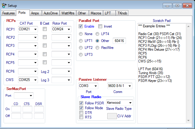
Ports
Contents
General
Use this tab to setup RCP and Parallel ports.
RCPs
Controls
This tab is for configuring the other Radio Control Programs (RCP) ports.
This page sets up and controls additional RCP programs. These are programs that can be used in addition to the Main RCP program setup on the "Ports" tab.
- CAT Port is used to select one end of a virtual serial port pair used to connect DDUtil with the RCP.
- B Cast (broadcast) if selected, will automatically output VFO A frequency and mode and VFO B frequency as described by Kenwood CAT commands IF & FB. These commands are output if VFO A or B frequency changes.
- Warning! The B Cast feature should only be used for a very few programs that don't poll the radio themselves but expect frequency and/or mode data to be present (Passive Listeners). And, by software developers for experimentation purposes. Use this feature with care as unexpected results may occur if used with some polling programs.
- RCP Rotor Port Select one end of a pair of virtual serial ports to connect your RCP's Rotor to DDUtil. See the following for a description of using Rotor Functions in DDUtil.
- Program Memo use this text box to keep track of what RCP's are attached to what ports. It's very easy to lose track of them.
Special Ports
The following ports are used for special purposes and not intended for normal RCP programs.
- CWS this is a special port configured especially for CW Skimmer users to be able to click in the CWS water fall window and QSY either VFO A or VFO B depending on how the radio is configured. This is especially handy for pile-ups when you hear the DX station (working split) call someone and you can see that person in the water fall window answering. With this feature just click the answering station and you've nailed the frequency where the DX station is listening.
- The following table defines the results of using different operating configurations when clicking the CWS water fall.
Radio Mode Sets VFO Freq RX1 RX2 Split Diver VFO A VFO B TX VFO x x x x x x x x x x x x x x x x x x
- Note: For more information on using the CWS Port see W9OY's Blog.
- Log 2, Log3 these ports are used for WriteLog when used in the SO2R mode. See the Contesting page for details.
Parallel Port
Note: see the LPT tab to configure the Band Data file and other controls.
SerMacPort
The Serial Macro Port is a special RS232 serial port used to send String (text) data to specially designed devices to use as command data. These devices are a new group of Micro Controllers used to control station activities like antenna switching and rig selection to name a few.
- Use the DDUtil macro command DDPS or DDPQ to send data to this port.
- Note: if a ; (semi-colon) is needed as a terminator for the string command use the DDPQ command.
- Additionally, this port has the ability to capture switch closures for the CD, CTS and DSR control lines. Switches attached to these lines can direct macros to perform functions that are free of focus issues.
- Use the following connection data when wiring up the switches. The resistor capacitor combination is required to de-bounce the switch contacts. Failure to do this can result in multiple events being fired when the switch is opened or closed and may cause multiple macro firings.
- Note: For best results use a separate capacitor/resistor combination for each control pin (1,6,8).
Connection Data
---------------
DB9F pin 4|7 -- 10k ohm resistor ----o |
                                       |-| switch
DB9F pins 1|6|8 ---------------------o |
                                     |
(CD #1, CTS #8, DSR #6)             --- .1 uFd
                                    --- capacitor
                                     |
DB9F pin 5 --------------------------o
Passive Listener
Slave Radio
- Follow SDR - Select this check box if you want to Slave another radio to PowerSDR in-lieu of a Passive Listener device. This feature allows another radio to follow PowerSDR's frequency, which is handy if your SDR is an old three (3) board stack or SoftRock. Be advised that in this mode receiver muting and antenna switching is required when transmitting from the slave radio or bad things will happen to your SDR.
- Follow Mode - Select this check box if you want the Slave radio to use the same mode as PowerSDR. If left unchecked the Slave radio will not follow the PowerSDR mode.
- Slave Radio Type - Select the radio type you wish to use as the slave.
Note: Right-click on the form background to display a menu of options and select "Slave Radio Info" for the radio models in each radio type. - PL/Radio Comm - Selects serial communication parameters for the Passive Listener port. Consult your radio users manual for this if necessary.
- DTR - Select this check box if your CI-V adapter or other equipment requires power from the DTR line. Check the manufactures instructions.
- RTS - Select this check box if your CI-V adapter or other equipment requires power from the RTS line. Check the manufactures instructions.
- CI-V Addr - Sets the appropriate CI-V Hex address if using an ICOM radio. Consult owner's manual for information on this.
Note: For more information on how to configure these functions see the How To section.
