Difference between revisions of "AntRtr"
From DDUtilV3
(→SteppIR) |
(→Rotor) |
||
| Line 5: | Line 5: | ||
This tab is dedicated to setting up the rotor(s) and a SteppIR antenna. | This tab is dedicated to setting up the rotor(s) and a SteppIR antenna. | ||
| − | ==Rotor== | + | ==Rotor Setup== |
If you plan to control a rotor from '''DDUtil''' this setup is mandatory. | If you plan to control a rotor from '''DDUtil''' this setup is mandatory. | ||
* '''Rotor''' (select) | * '''Rotor''' (select) | ||
Revision as of 18:27, 9 February 2017
General
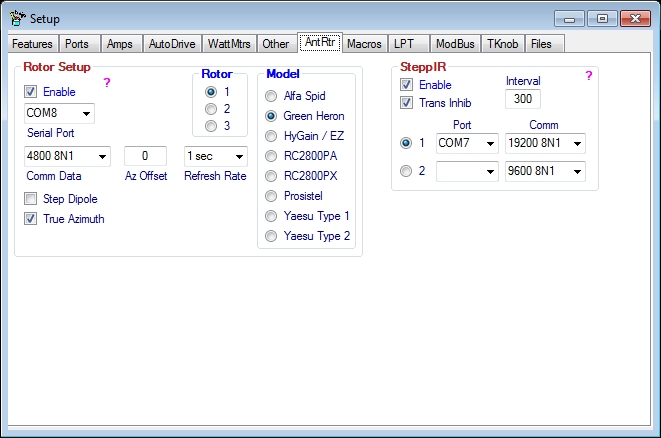
This tab is dedicated to setting up the rotor(s) and a SteppIR antenna.
Rotor Setup
If you plan to control a rotor from DDUtil this setup is mandatory.
- Rotor (select)
- Select the rotor you want to be the active rotor.
- Warning!
- If you select a rotor that has no port assigned, the Enable check box will be un-checked thereby disabling all rotor activity. Watch this as it can bite you.
- Notes:
- Only one rotor may be used at a time.
- Rotor model, port, speed, comm data and Azimuth Offset are saved for each rotor selection.
- Model
- Select the rotor model you are using for the selected rotor.
- Speed
- Select a speed setting for the selected rotor if your rotor (Orion, Yaesu) is one of the models that require a speed be set.
- Serial Port
- Select the hardware serial port your rotor control box is connected to for the selected rotor.
- Com Data
- From the drop down list select the proper communication setting to match your rotor control box for the selected rotor.
- Enable
- Select the Enable check box to complete the Rotor setup.
- Note: There is only one Enable control for all three rotors. It must be selected at all times for the rotor functions to work.
- SteppIR Dipole
- Select this check box if you have a SteppIR yagi antenna with the 80 meter dipole option.
- DDUtil will modify the beam heading when on the 80 meter band to be Broad Side to the station heading selected.
- Will take the shortest path to the Broad Side position from the last heading entered.
- True Azimuth
- Select this check box if you want the antenna heading displayed to be the intended antenna direction. If un-checked the actual rotor position (intended direction +/- offset) will be displayed.
- Notes:
- This check box only applies if the offset is other than zero (0).
- Selected is the default condition.
- Az(imuth) Offset
- If you need an azimuth correction for the selected rotor enter it here. Offset numbers must be in the range of -180 to 180 degrees. Numbers may be entered as either 1, 2 or 3 digits or -1, -2, or -3 digits. i.e. 25 or -25.
- The new heading will be either added or subtracted to the desired heading before being sent to the rotor.
- Refresh Rate
- This is the rate which DDUtil scans the Active rotor port for bearing information. Using this method guarantees that even if the rotor is moved manually the correct bearing data will be displayed in DDUtil.
SteppIR
This setup is for users that want to use the extended features of the SteppIR control box beyond just following frequency. These features include:
- Changing the beam direction to Forward, 180 (Reverse), Uni-directional and 3/4 mode (verticals only).
- Home the elements.
- Calibrate the antenna.
Additionally, the message Transmit Inhibited is displayed near the top of the DDUtil form whenever the antenna is adjusting and the radio is disabled from transmitting during this time.
- Select the port number connected to the SteppIR controller Data Out port.
- Select the Comm setting to match your setup in the controller. For best response use 19200 8N1.
- Select the Trans Inhib (Transmit Inhibit) check box to disable PSDR from transmitting while the antenna is moving
